

DIY rocket stove for camping
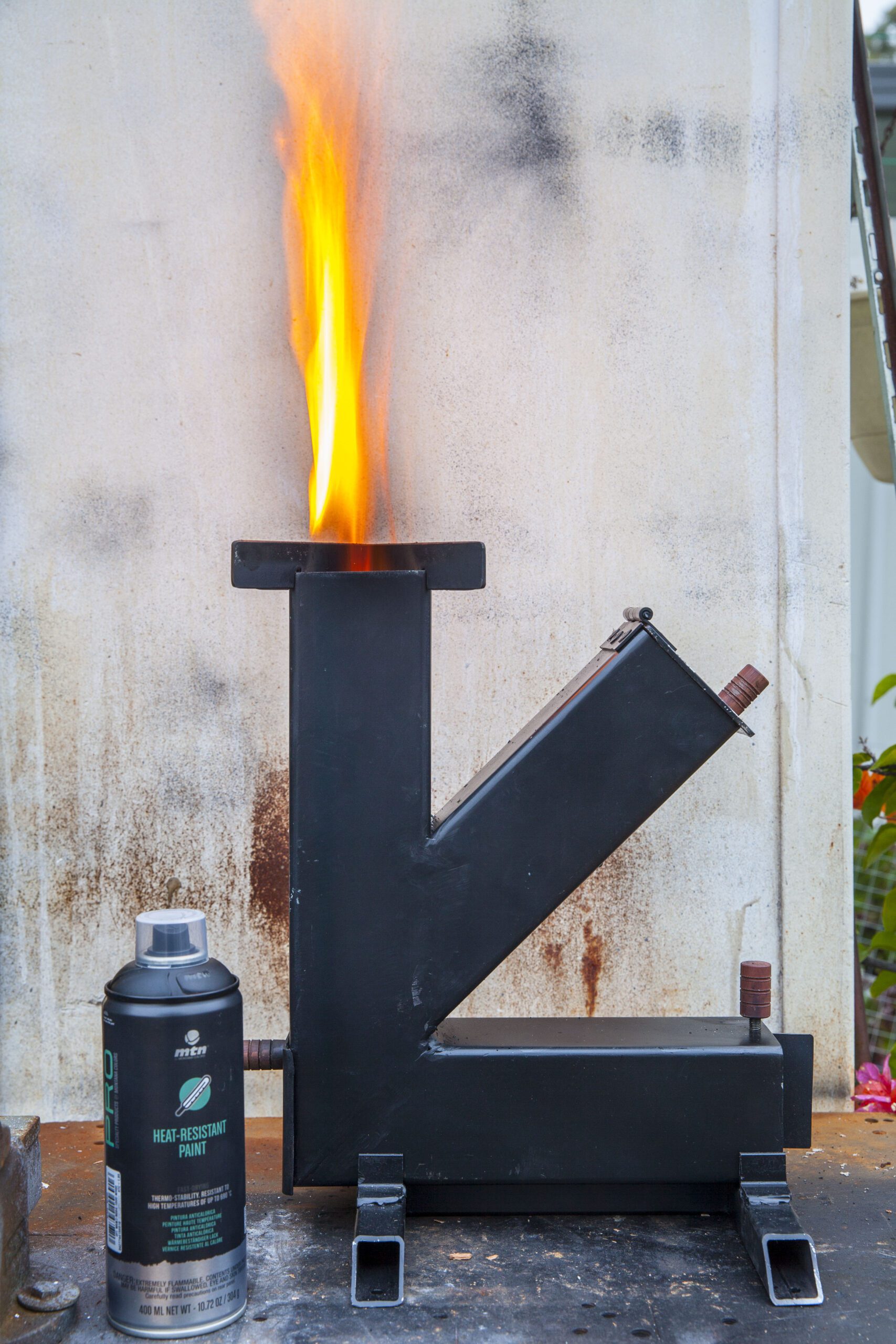
For most of us, having enough space in our vehicles to store gear for a hunting trip can be challenging, but this ‘lay flat’ rocket stove is an easy-to-store option to take for the bush camp.
The design has six parts: main stove body, detachable base, two-part hob, ash draw and grid, butterfly valve to regulate air intake and a lid for the top of the wood feed tube. Apart from the welding there are no special skills required for production.
Tool wise, an angle grinder with suitable metal cutting discs, drill, ruler, square and pencil are all you need. If a metal cutting saw is available, it can make easy work of the heavier cutting.
Materials
- 1m length of 75mm x 75mm x 2.5mm RHS
- 700mm length of 25mm x 25mm x 2mm RHS
- 400mm length of 25mm x 3mm flat bar
- 250mm length of 5mm round bar
- 110mm length of 20mm x 20mm x 3mm angle
- 2mm sheet metal to cut an 80mm x 80mm and 70mm x 62mm section
- Wire mesh to cut an 125mm x 60mm and 95mm x 70mm section
- 70mm butt hinge
- 100mm length of wooden dowel rod
- 2 x 25mm x 8-gauge self-tapping screws
- Length of steel mesh or steel cooling rack
- 8mm length of compression spring that will slip over a 5mm diameter rod.

The build
The first step is to measure and cut the four sections of 75mm rectangular hollow section (RHS) steel to make the body and ash draw. Measure a 330mm length, mark a 45-degree line, the 330mm being the long side; this section forms the heat tube. You can cut this section off or the other three sections can be marked out and all four sections cut off together.
The second section is 230mm long and measured along the long side of the 45-degree cut on the RHS; the initial 45-degree cut serves both the fire tube and 230mm wood feed sections. The opposite end of the wood feed tube is cut off square.
The next section, that forms the air intake tube, is 260mm in length and has a 45-degree section cut off one end, the other end is cut off square.
The last section is 110mm in length; this will form the ash draw body.
The next step is to mark out a rectangular section in the base of the heat tube, 103mm long and 71mm wide, this should be marked out 6mm up from the base on the short face. To complete the three body components, carefully cut out the rectangle section with an angle grinder.


The last task before welding the body together is to drill two 5.5mm holes top and bottom in the open end of the air tube 10mm back and in the centre of the tube; these are for the butterfly valve shaft.
Here is where it all starts to come together. Carefully fit the heat tube section to the air tube section, making sure the two 45-degree faces are in perfect alignment and both sections are square to each other, clamp them in position and tack weld them together. Next, the wood feed tube must be positioned. This is best done with the heat tube on its back with the air tube vertical. The wood feed tube 45-degree face is positioned level with the top of the 6mm section on the heat tube, check the alignment then tack weld into position. If all checks out correctly the three sections can be welded together.
To complete the body of the stove a 67mm high x 69mm wide section is cut out of the back of the heat tube at the base to allow fitment of the ash draw.
To build the ash draw from the 110mm section of RHS requires some work. The draw body dimensions are 67mm high and 110mm long, requiring an 8mm x 110mm section to be cut from the RHS, with part of this used to make the front of the draw. Here is where the additional work comes into play, as the draw body must be reduced in width to 68mm. This requires a 7mm section cut out along its length to allow the draw to slide freely into the base of the heat tube. Once the 7mm strip is removed, the draw body is welded back together.
To make the draw face, a 75mm section is cut from the 8mm x 110mm section and given this section has rounded edges will give the draw face a neat wrap-round finish to the draw, however it will require widening. The draw face is cut in half vertically and a 7mm wide piece cut from the remaining 110mm section is positioned between the two halves and welded together. The draw face is positioned on the draw body and welded in place. To complete the draw the excess welds are ground flush.
Next stage is to form the ash grid and fit it into the draw. Two lengths of 5mm round bar are cut 67mm in length and fitted into holes drilled into the draw body 7mm from the top and spaced 92mm apart, the front bar being 7mm from the inside of the draw face. Cut a section of the steel mesh or cooling rack (about $8 from the supermarket) 135mm long x 58mm wide, with 15mm on each end folded down at right angles to fit over the two cross supports. To make easy work lighting the stove and have enough mesh left over, a small hat shaped basket can be folded large enough to hold a standard sized fire lighter, clipped into the underside of the ash mesh.


All that remains to complete the rocket stove is to cut out the wood feed tube lid from 2mm sheet metal, with 80 x 80mm square being the required size. This is mounted to the top of the wood feed tube with a 70mm butt hinge, with a self-tapping screw placed in the bottom centre of the lid to fasten the wooden dowel knob.
To regulate the air flow through the stove, which in turn regulates the heat generated, a butterfly type valve is installed in the front of the air tube. A piece of sheet metal is cut 68mm x 63mm, along with a 95mm length of the 5mm round bar and a 5mm spacer. A 5mm hole is drilled in the centre of the valve plate through which the plate is welded to the valve spindle shaft, to assemble the valve – the shaft is fed down through the top hole then through the spacer and through the bottom hole flush with the bottom of the tube. The valve plate is positioned on top of the spacer and centred inside the air tube, once in position it is welded to the shaft through the hole in the centre of the plate. To complete the valve a small length of compression spring is placed on top of the shaft and the wooden dowel knob fitted. The spring places a small amount of tension on the valve to hold it in the required position.

The detachable base parts are quite straight forward to cut to size and weld together, the H section is made with the 25mm x 25mm x 2mm RHS. The two cross sections are 520mm in length with 45-degree angles on each end. These are centre drilled if additional support is needed; cut down 5mm tent pegs to be placed through the holes and driven into the ground, for rock solid support if a heavy pot is in use. The centre section of the H is 175mm in length and is welded to the centres of the cross sections. Cut four 25mm long pieces of the angle plus another 60mm long. Place the stove on the centre of the base and mark the positions of the four pieces of angle, allowing a little extra width so the body will slide in freely, then weld them in place. Lastly, cut a 7mm slot in the centre of one side of the 60mm length of angle to allow the butterfly valve spacer to slide through. Re-mount the stove onto the base and slide the air tube flush with one end of the base, fit the 60mm angle section to the end of the base with the 7mm slot centred around the valve spacer and weld it into position.
Finally, cut 2 x 180mm long sections of the flat bar to make the hob, in the centre of each cut a 4mm wide slot 12mm long at right angles, take one piece, turn it over and place it into the slot of the other. This will result in a flat surface for pots etc to sit on without rocking.
To complete the hob, position the ends of the flat bar in the centre of the corners of the heat tube and mark their positions on the hob sections, again cut 4mm wide slots at right angles 12mm long. If all has gone to plan the hob should fit snuggly into the top of the heat tube.
With all the above completed, the various components are sprayed with flat black high temperature exhaust paint.
The all-up weight is a manageable 5.6kg and with the two sections of the hob removed, these can be stored in the body of the stove, so they don’t get lost. Along with the base removed the rocket stove takes up minimal space given its size.
The rocket stove is very efficient, with a small bunch of twigs sufficient to half fill the wood feed tube – more than enough to boil 1L of water in a few minutes.
In all, a worthwhile project and a handy addition to the camping gear that eliminates the need to always light a full-blown campfire.

Turbo-mode!
The rocket stove has certainly been a great asset when preparing hot meals out bush, requiring surprisingly little wood for general camp cooking.
After a couple attempts at cooking Asian-type meals over the rocket stove using a wok, it soon became obvious that a significant increase in heat would be beneficial. In keeping with the modular concept where all the components of the rocket stove come apart for easier storage when on the road, the idea of a detachable turbo unit to increase the air flow through the rocket stove evolved.
As it turned out the solution lay in an old desktop computer, extracting a suitable sized computer fan and mounting piece. To mount the fan in a short length of 75mm x 75mm RHS, the fan mount needs to be modified. Cut the plastic tubing section back to 25mm in length and trim the top, bottom and sides off to form four semi-circular corner sections that are a firm fit into the RHS. To complete the module, four lengths of 6mm round bar are cut and welded into the four corners of the RHS with 60mm protruding; these form a firm attachment into the air tube of the rocket stove.
This addition intensely increases the heat generated, so much so that additional wood is required, which isn’t surprising. While the butterfly valve does a reasonable job of taming the air flow, something more efficient is worth considering.
One aspect to keep in mind is the increased air flow from the longer lengths of wood in the wood tube burning back up the tube. To prevent this from occurring a simple adjustable fire wall can be constructed, which also helps in moving the wood towards the fire as it burns down.
Having the ability to vary the fan motor speed provides far better, step-free, control over the air put through from the fan. Available from your local electronics store, a PWM 12VDC 5A speed controller kit is perfect. It comes with a suitable case, on/off switch, 12v LED and a plug and socket.
As the computer fan draws very little current, the smallest 12v battery is actually all that is required for power, making it portable and ideal in a camp situation where it can be connected to any 12v dc supply.
Being able to easily regulate the heat means the detachable turbo module has certainly been a worthwhile addition to camp cooking with the rocket stove. Running the turbo at higher speeds does require additional wood, and it’s worthwhile thinking about adding a modest amount of hardwood charcoal as the icing on the cake.

*Jump on YouTube for help making the main K-frame or get in touch if stuck with anything via [email protected]
Share this article
Related
Articles


Fox hunting with a button whistle


Related
Recipes
Sorry, no related items found.